IDVP.01 Rotor Vibration Measurement Module
Product description
IDVP.01 Vibration Monitoring Module
The IDVP.01 Vibration Monitoring Module (VMM) is designed for non-contact measurement of relative shaft displacement and relative shaft vibration displacement, as well as for monitoring the peak-to-peak value of the relative vibration displacement of rotating parts of industrial equipment (units, machines, and mechanisms).
The IDVP.01 VMM can be used either as a standalone module for measurement, alarm indication, and machinery protection against controlled parameters exceeding preset alarm and trip levels, or as part of the PULS 1.02 monitoring and measurement system, a Process Automation System (PAS), or other industrial automation systems.
Composition of the IDVP.01 Vibration Measurement Module
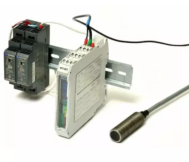
The IDVP.01 Vibration Monitoring Module (VMM) consists of:
- a non-contact, single-channel eddy-current primary transducer (probe), model IP-IP;
- a signal conditioner, model FP-IP.
The IDVP.01 VMM provides the following functions:
- continuous measurement of the current values of relative shaft displacement and relative shaft vibration displacement of rotating equipment;
- monitoring and alarm indication for:
- peak-to-peak relative shaft vibration displacement exceeding preset alarm/trip levels (three levels);
- vibration jump detection;
- low-frequency (LF) vibration level exceeding the preset threshold;
- transmission of measured relative shaft displacement, peak-to-peak relative shaft vibration displacement, as well as the amplitudes and phase angles of the harmonic components of the relative shaft vibration signal via an RS-485 serial interface to external monitoring and visualization systems;
- indication of primary transducer (probe) faults, including short circuit and open circuit conditions in the communication line between the primary transducer and the signal conditioner;
- transmission of alarm events and diagnostic information via the RS-485 serial interface to external monitoring and visualization systems;
- generation of discrete output signals indicating vibration jump events, excessive low-frequency vibration, and peak-to-peak relative shaft vibration displacement reaching preset alarm/trip levels for external alarm systems;
- generation of a standard 4–20 mA analog current output proportional to the peak-to-peak relative shaft vibration displacement;
- generation of a 0–3 V analog voltage output proportional to the instantaneous values of relative shaft vibration displacement and relative shaft displacement;
- automatic compensation for ambient temperature effects (temperature compensation) on measured relative shaft displacement and relative shaft vibration displacement;
- automatic self-diagnostics and functional integrity monitoring.
Characteristics of the IDVP.01 Vibration Monitoring Module
| Parameter | Specification |
|---|---|
| Relative vibration displacement peak-to-peak measurement range, µm | 20¹ – 4000² |
| Relative displacement measurement range, µm | 20¹ – 4000² |
| Frequency measurement range of relative vibration displacement peak-to-peak value, Hz | 0.05 – 500³ |
| Reference measurement frequency, Hz | 80⁴ |
| Maximum permissible basic relative measurement error of relative vibration displacement peak-to-peak value at the reference frequency, % | ±5 |
| Amplitude-frequency response (AFR) non-uniformity, max, % | ±3 |
| Maximum permissible basic relative measurement error of relative displacement, % | ±5 |
| Nominal conversion factor of relative vibration displacement/displacement, mV/µm | 0.5⁵ |
| Maximum deviation of the actual conversion factor value of relative vibration displacement at the reference frequency, max, % | ±5 |
| Maximum deviation of the actual conversion factor value of relative displacement, max, % | ±5 |
| Relative vibration displacement signal phase measurement range, degrees | 0–360⁶ |
| Maximum permissible phase measurement error of the relative vibration displacement signal, max, degrees | ±3 |
| Technological gap¹ ST between the eddy-current probe tip and the monitored surface, mm | 1.0 |
| Initial setting gap⁷ Su according to LCD indication readings, mm | 2.0 ± 0.25 |
| LCD information refresh time, max, s | 0.5 |
| Load resistance for 4–20 mA output signal, max, Ω | 500 |
| Output analog voltage signal range, V | 0–3 |
| Number of discrete (logic) outputs | 5 |
| Output discrete signals of the module: | |
| – DC voltage, max, V | 12 |
| – Current, max, A | 1 |
| Output type | Open collector |
| Digital communication interface types | RS485 (ModBus RTU) |
| Degree of protection: | |
| – Primary measuring transducer (PMT) | IP67 |
| – Measuring converter (MC) | IP20 |
| Dimensions: | |
| – PMT diameter; body length without stem, mm | 18; 55 |
| – MC height × width × depth, mm | 114.5 × 17.5 × 99 |
| Weight: | |
| – PMT without cable, max, g | 175 |
| – MC, max, g | 125 |
-
Measurement range with standardized metrological characteristics. The actual measurement range is from 10 µm to 5 mm.
-
The maximum upper measurement limit of the relative vibration displacement peak-to-peak value together with relative displacement shall not exceed 4 mm.
-
Frequency measurement range with standardized metrological characteristics. The actual frequency measurement range of the relative vibration displacement peak-to-peak value is from 0.05 Hz to 1500 Hz.
-
Manufacturing with a different reference frequency value is available upon Customer request.
-
The DC component of the output analog voltage signal is proportional to the relative displacement, while the AC component is proportional to the relative vibration displacement.
-
Amplitudes and phases of harmonic components of vibration displacement are measured only when a keyphasor signal is applied to the corresponding input of the measuring converter (MC).
-
Initial setting gap between the tip of the primary measuring transducer (PMT) and the monitored surface:
S₀ = ST + Su.
Operating conditions for the PP-IP primary measuring transducer (PMT):
-
ambient temperature (air, water vapor, oil vapor): from −30 °C to +100 °C (short-term up to +120 °C);
-
electromagnetic field strength: up to 400 A/m;
-
relative air humidity: up to 98% at +35 °C; moisture condensation on the surface of the primary measuring transducer is permissible;
-
atmospheric pressure: from 84 kPa to 106.7 kPa.
Operating conditions for the FP-IP measuring converter (MC):
-
ambient air temperature: from +5 °C to +60 °C;
-
electromagnetic field strength: up to 100 A/m;
-
relative air humidity: up to 80% at +25 °C; moisture condensation is not permitted;
-
atmospheric pressure: from 84 kPa to 106.7 kPa.
Service life of the IDVP.01 Vibration Monitoring Module (VMM): 10 years from the date of delivery to the Customer.
Warranty operating period of the IDVP.01 Vibration Monitoring Module (VMM): 24 months from the date of commissioning.
Warranty storage period of the IDVP.01 Vibration Monitoring Module (VMM): 36 months from the date of purchase.
Installation of the PP-IP Primary Measuring Transducer for Rotor Vibration Displacement Monitoring